Accurate sheet metal parts begin with the correct flat pattern. When a sheet is bent, the material on the inside of the bend compresses while the outside stretches, so the finished part cannot be calculated by simply adding the flange dimensions together.
This guide explains how to calculate sheet metal bend allowance, K-factor, bend deduction and flat pattern length. It also shows how bend radius, material thickness, tooling and actual press brake setup affect the numbers used in CAD and production.
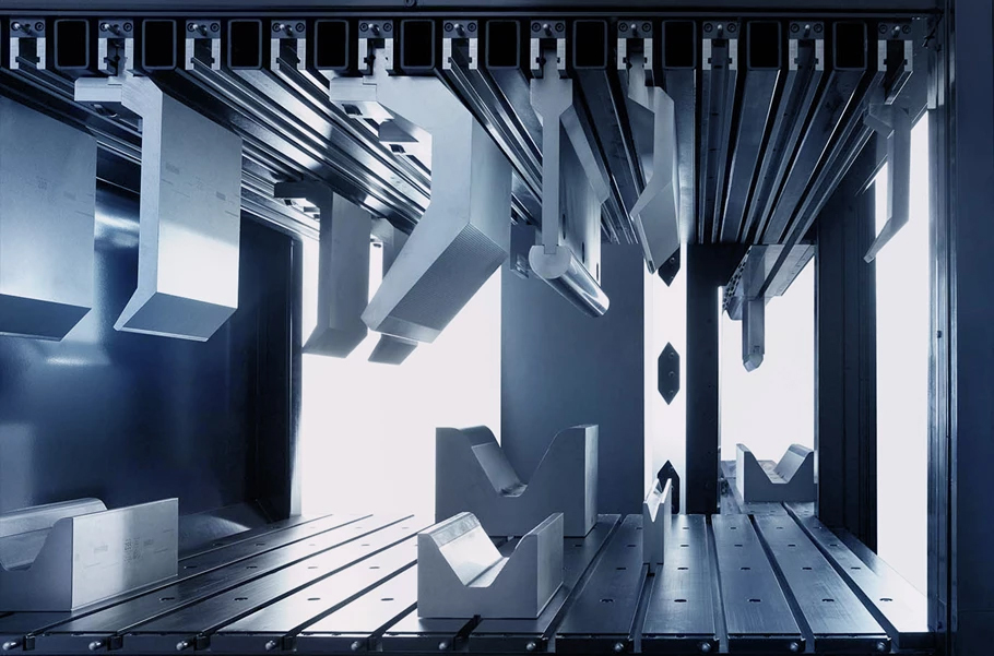
Bend allowance calculations should reflect the actual material, tooling and press brake setup used in production.
Bend allowance is the length of the bend measured along the neutral axis of the material.
The K-factor describes where that neutral axis lies through the material thickness. Once bend allowance is known, it can be used with the outside dimensions of the part to calculate bend deduction and the required flat blank length.
When sheet metal is formed, the inner surface of the bend is compressed and the outer surface is stretched. Between these two zones is a theoretical neutral axis whose length changes much less during bending.
Bend allowance, usually abbreviated as BA, represents the arc length of this neutral axis through the bend. It is used to determine how much material must be included in the flat pattern before forming.
If bend allowance is incorrect, finished flange lengths can be too long or too short, holes may move out of position, mating parts may no longer align, and repeated production can generate avoidable scrap.
K-factor is a dimensionless ratio that describes the position of the neutral axis relative to the sheet thickness.
The neutral axis does not necessarily remain at the exact center of the sheet during forming. Its position depends on the bending process and actual deformation conditions.
For this reason, a K-factor should not be selected only from a generic material name. For repeat production, the most reliable value is normally developed from the actual material, thickness, bend radius, tooling and process used in your own shop.
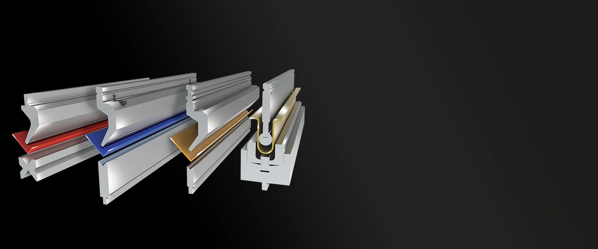
V-die opening, punch geometry and the resulting inside radius influence the bending conditions used for flat-pattern calculations.
When K-factor is used, bend allowance can be calculated with the following equation:
| Symbol | Meaning | Unit |
|---|---|---|
| BA | Bend allowance | mm or in. |
| A | Bend angle through which the material is formed | degrees |
| R | Inside bend radius | mm or in. |
| K | K-factor | dimensionless |
| T | Material thickness | mm or in. |
This formula follows the K-factor bend allowance method described in SOLIDWORKS sheet metal documentation . CAD software may also use bend tables, explicit bend allowance values or bend deduction values instead of a single K-factor.
Consider a 90° bend with the following values:
Material thickness T = 2 mm
Inside bend radius R = 2 mm
K-factor = 0.40
Bend angle A = 90°
BA = (π / 180) × 90 × (2 + 0.40 × 2)
Bend Allowance ≈ 4.40 mm
The 0.40 K-factor in this example is used only to demonstrate the calculation. It should not be treated as a universal value for every 2 mm sheet or every material.
The table below keeps the same 90° bend, 2 mm thickness and 2 mm inside radius, but changes only the K-factor. This shows why using the wrong K-factor can gradually shift finished dimensions.
| K-Factor | Bend Radius | Thickness | Calculated BA |
|---|---|---|---|
| 0.30 | 2 mm | 2 mm | 4.08 mm |
| 0.35 | 2 mm | 2 mm | 4.24 mm |
| 0.40 | 2 mm | 2 mm | 4.40 mm |
| 0.45 | 2 mm | 2 mm | 4.56 mm |
| 0.50 | 2 mm | 2 mm | 4.71 mm |
Bend deduction, abbreviated as BD, is used when finished flange dimensions are measured to the outside theoretical intersection of the bend.
Instead of adding bend allowance directly to tangent lengths, bend deduction is subtracted from the finished outside dimensions to determine the required flat blank.
For a standard bend-angle convention, the outside setback can be calculated as:
| Item | Bend Allowance | Bend Deduction |
|---|---|---|
| Meaning | Arc length through the neutral axis | Amount subtracted from outside dimensions |
| Typical Use | Calculating developed lengths from tangent dimensions | Calculating flat length from finished outside dimensions |
| Affected By | Angle, radius, thickness and K-factor | Bend allowance plus outside setback |
Suppose a 90° bent part has the following finished outside dimensions:
Outside leg A = 50 mm
Outside leg B = 30 mm
Thickness T = 2 mm
Inside radius R = 2 mm
K-factor = 0.40
Bend angle = 90°
BA ≈ 4.40 mm
OSSB = 4.00 mm
BD = 2 × 4 − 4.40 ≈ 3.60 mm
This example assumes the 50 mm and 30 mm legs are measured as finished outside dimensions to the theoretical sharp. If drawing dimensions are defined differently, use the corresponding CAD or fabrication convention.
The K-factor used in CAD should correspond as closely as possible to the production process. A different V-die opening can change the naturally formed inside radius during air bending, which in turn changes bend allowance and bend deduction.
Punch radius, material strength, grain direction, bend angle and whether the operation is air bending, bottoming or coining can also change the final result.
For detailed tooling selection, see LISTEN's press brake die selection guide.
Bend radius describes the inside curvature of the formed part. Bend allowance describes the developed length of material through that bend.
If your main question is whether a chosen radius may create cracking or forming problems, that is a separate design issue from flat-pattern calculation. See LISTEN's sheet metal bend radius and cracking guide for that topic.
For repeat production, a test bend is usually more valuable than copying a generic K-factor from the internet.
If you know the actual bend allowance from a test part, K-factor can be estimated using:
Modern CAD systems allow sheet metal designers to control flat-pattern development using K-factor, bend allowance, bend deduction or bend tables.
SOLIDWORKS allows bend allowance parameters to be defined through K-factor, bend allowance, bend deduction or bend tables. Autodesk Fusion sheet metal rules similarly include thickness, bend radius and K-factor as configurable sheet metal parameters.
Reference: SOLIDWORKS Bend Parameters and Autodesk Fusion Sheet Metal Rules .
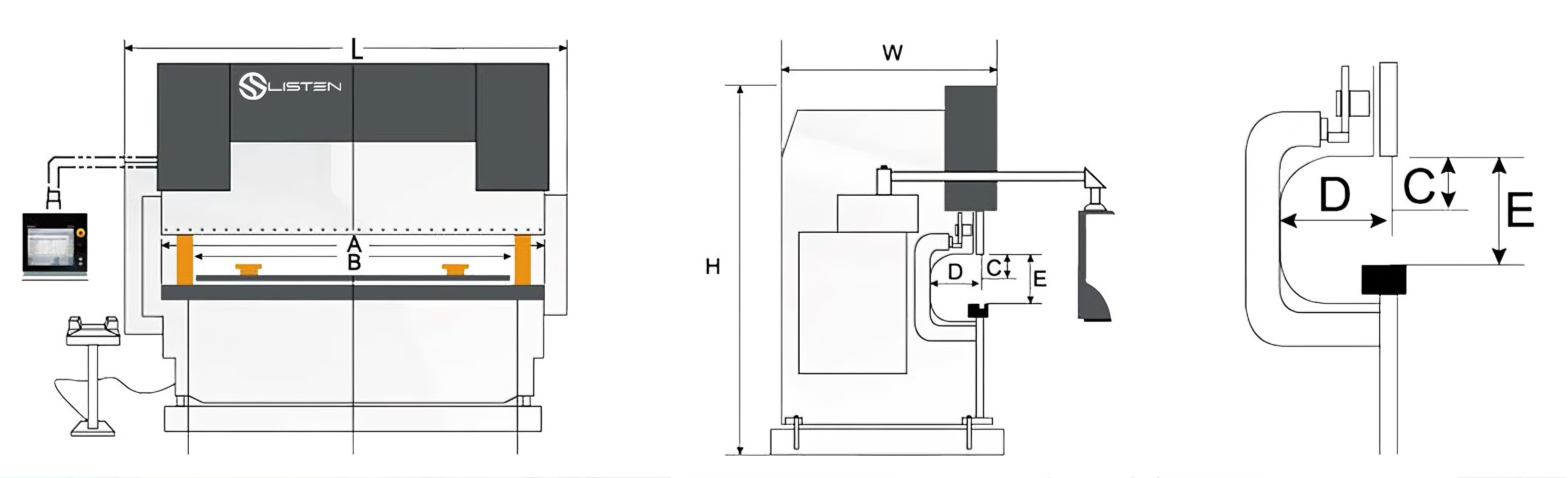
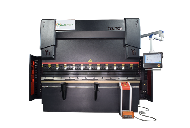
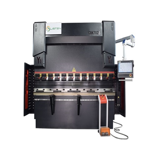
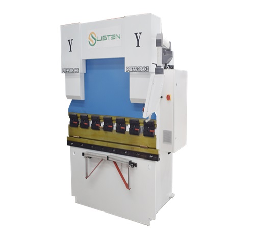
LISTEN offers multiple press brake force and working-length configurations for different sheet metal bending requirements.
Correct bend allowance does not replace correct machine setup. The production process must still match the assumptions used in the flat-pattern calculation.
Tooling, working length, backgauge positioning, ram control and repeatability all influence whether the calculated blank becomes the intended finished part.
For production equipment, see LISTEN's press brake range. If you need to determine the required bending force before selecting a machine, use our press brake tonnage calculation guide.
| Step | Check | Why It Matters |
|---|---|---|
| 1 | Confirm material and thickness | Defines the basic bending condition |
| 2 | Choose punch and V-die | Influences radius and forming behavior |
| 3 | Confirm bend angle and radius | Required for BA and BD calculation |
| 4 | Apply K-factor or bend table | Determines developed bend length |
| 5 | Generate flat pattern | Defines laser-cut or sheared blank geometry |
| 6 | Perform first-piece inspection | Allows correction before batch production |
Bend allowance is the developed arc length of the bend measured along the neutral axis. It is used when calculating the required flat length before the sheet is formed.
When K-factor is used, BA = (π / 180) × A × (R + K × T), where A is bend angle, R is inside radius, K is K-factor and T is material thickness.
K-factor is the ratio between the distance from the inside bend surface to the neutral axis and the total sheet thickness.
No single value is accurate for every setup. The effective K-factor can change with material condition, thickness, bend radius, V-die opening and bending method. A test bend is recommended for repeat precision work.
Bend allowance represents the developed length through the bend, while bend deduction is the amount subtracted from finished outside dimensions to obtain the flat blank length.
It can. During air bending, V-die opening influences the naturally formed inside bend radius, and that radius is one of the variables used in bend allowance calculations.
Yes. CAD systems such as SOLIDWORKS and Autodesk Fusion can generate sheet metal flat patterns using K-factor, bend allowance, bend deduction or material-specific bend tables. The values still need to match the real manufacturing process.
Common causes include an incorrect K-factor, a different actual bend radius, material variation, springback, tooling changes or dimensions being measured using a different inside/outside convention.
A K-factor is convenient for general modeling and initial calculations. For repeat production across known materials, thicknesses and tooling combinations, a validated bend table can provide better consistency.
Send LISTEN your drawing, material grade, thickness, bend angle, inside radius and expected production volume. Our team can help evaluate the press brake and tooling configuration required for your bending application.
VIEW PRESS BRAKE SOLUTIONS → SEND YOUR PART DRAWING